|
1. Verfahren |
1. Procedures |
|
1.1 BTA Verfahren |
1.1 BTA prcocedure |
| Das Tiefbohren mit BTA-Werkzeugen (von ca. | Deep hole boring using BTA tools (diameters ranging |
| Ø 6mm bis Ø 2000mm) ist ein spanabhebendes | from approximately 6mm to 2000mm) is a cutting |
| Fertigungsverfahren für Bohrungstiefen im allgemei- | procedure for bore depths of generally l=3·D and |
| nen ab l=3·D. Für Bohrungen kleiner als Ø 40mm | above. For bore diameters of less than 40mm, other |
| kommen auch andere Tiefbohrverfahren in Betracht | deep-boring procedures are possible. |
| Das Verfahren ist in Bild 1 dargestellt. | The procedure is illustrated in Figure 1. |
| Die Zufuhr des Kühlschmierstoffes (KSS) geschieht | The coolant is supplied under pressure from the out- |
| von außen unter Druck in einem Ringraum zwischen | side into an annular space between the wall of the |
| Bohrungswand und Bohrrohr, der Spanabfluß erfolgt | bore an the boring tube. Chips are removed through |
| durch das Spanmaul und das Innere des Bohrrohres. | the chip-mouth of the tool and the inside of the boring |
| tube. |
| 1.2 Ejektor Verfahren | 1.2 Ejector prcocedure |
| Das Tiefbohren mit Ejektor-Werkzeug (von ca. | Deep hole boring with ejector tools (diameters rang- |
| Ø 18,40mm bis ca. Ø 250mm) ist eine Variante | ing from approximately 18,40mm to approximately |
| BTA-Verfahrens. Das Verfahren ist in Bild 2 darge- | 250mm) is a variant of the BTA procedure. The pro- |
| stellt. | cedure is illustrated in Figure 2. |
| Die Zufuhr des Kühlschmierstoffes erfolgt in einem | The coolant is supplied via an annular space between |
| Ringraum zwischen dem Bohrrohr und einem Innen- | the boring tube and an inner tube (double-tube proce- |
| rohr (Zweirohrverfahren). Der Kühlschmierstoff tritt | dure). The coolant comes out at the sides of the bor- |
| am Bohrkopf seitlich aus, umspült diesen und fließt | ing head, washes round the same, and flows back |
| mit den Spänen im Innenrohr zurück. Ein Teil des | through the inner tube, taking the chips along with it. |
| Kühlschmierstoffes wird über eine Ringdüse in das | Part of the coolant is fed into the inner tube via an an- |
| Innenrohr eingeleitet. Durch den entstehenden Unter- | nular nozzle. The backflow results from an under- |
| druck am Spanmaul wird der Rückfluß ermöglicht | pressure building up at the chip-mouth (ejector ef- |
| (Ejektor-Effekt). | fect). |
| Zwischen Werkstück und Bohrbuchse ist keine Ab- | No sealing is required between the workpiece and the |
| dichtung nötig, daher eignet sich des Ejektorbohren | start bush. The ejector-boring system ist therefore par- |
| besonders für den Einsatz auf Drehmaschinen, Bohr- | ticularly suited for use with turning machines, hori- |
| und Fräswerken sowie Bearbeitungszentren. | zontal boring machines, millers, an machining cen- |
| tres. |
| 1.3 Einlippenbohrverfahren | 1.3 Single lip gun-drilling |
| Das Einlippenbohren wird im Durchmesserbe- | Gun-drilling is used in the range of diameters |
| reich von ca. 0,8 mm bis 40 mm eingesetzt. | between approximately 0,8 mm and 40 mm. Cooling |
| Die Zufuhr des Kühlschmierstoffes (KSS) er- | lubricant is delivered through one or more holes which |
| folgt durch eine oder mehrere Bohrungen inner- | pass through the tool shank. The mixture of chips and |
| halb des Werkzeugs. Die Abteilung des KSS- | cooling lubricant ist removed along a flute or longitu- |
| Spänegemisches geschieht durch eine Längs- | dinal groove (bead) on the outside of the tool shank. |
| Bild 2.1 zeigt die wesentlichen Merkmale diese | Figur 2.1 shows the main characteristics of this |
| fahrens. | method. |
| 1.4 Vorteile | 1.4 Advantages |
| Vorteile der in Abschnitt 1.1 und 1.2 beschriebenen | The deep-boring procedures described in Section 1.1 |
| Verfahren zur Herstellung von tiefen Bohrungen | and 1.2 above offer the following advantages: |
| sind: | |
| - sehr hohe Zerspanleistung durch den Einsatz von | - extremely high cutting capacity thanks to tungsten |
| Hartmetall als Schneidstoff | carbide being used as cutting material |
| - ideale Bedingungen bezüglich Kühlung und | - ideal conditions with regard to cooling and lubri- |
| Schmierung | cation |
| - kontinuierliche Spanabführung, daher keine Aus- | - continuous chip removal, no need for chip- |
| spanhübe/Ausspanvorgänge notwendig | removal strokes/processes |
| - kürzere Hauptzeiten | - reduced cutting times |
| - hohe Bohrungsqualität hinsichtlich Durchmesser- | - high quality of bore in terms of diameter toler- |
| toleranz, Oberflächengüte und geometrischer | ance, surface quality, and geometrical accuracy |
| Formgenauigkeit | |
| - hohe Fluchtgenauigkeit, geringer Bohrungsver- | - high accuracy of alignment, low eccentricity of |
| lauf | the bore |
| - Ersetzen mehrerer Arbeitsvorgänge - z.B. Vor- | - replacement of several processes, e.g. rough-bor- |
| bohren, Aufsenken, Reiben-durch einen Arbeits- | ing, boring, reaming, by one process, deep hole |
| vorgang Tiefbohren | boring |
| - Bearbeiten schwer zerspanbarer Werkstoffe | - cutting of hardly machinable materials |
| - große Bohrtiefe (als max. Bohrtiefe ist etwa das | - deep bores (The max. achievable depth is approxi- |
| 250fache des Borhdurchmessers möglich, wobei | mately 250 times the bore diameter. However, the |
| das Verfahren jedoch auch bei kurzen Bohrtiefen | procedure is also cost-efficient for short bore |
| wirtschaftlich ist) | depths) |
| - geringe Gratbildung beim Aus- und Überbohren | - reduced formation of burrs during the boring or |
| von Querbohrungen (bzw. beim Durchdringen be- | re-boring of cross-bores (penetration of existing |
| reits vorhandener Konturen) | contours) |
| - keine Beeinträchtigung der erzeugten Oberfläche | - no damage to the surface produced by chip re- |
| durch Spanabtransport | moval |
| - Bohrrohr torsionssteifer als der gesickte Werk- | - boring bar stiffer against torsion than the kidney |
| zeugschaft beim Einlippenbohrer | shaped shank of a gun drill |
| 1.5 Kühlschmierung | 1.5 Cooling lubrication |
| Die Kühlschmierung erfordert verfahrensbedingt be- | It is in the nature of the procedure that cooling lubri- |
| sonderen Aufwand. Zum Kühlen und Schmieren | cation is highly demanded. Large volume flows are |
| werden große Volumenströme benötigt, die zusam- | needed for cooling and lubrication, which are re- |
| men mit den anfallenden großen Spanmengen durch | moved through the boring bar along with the large |
| das Bohrrohr heraustransportiert werden. Hierzu sind | quantites of chips being produced. Depending on the |
| je nach Durchmesser hohe Drücke erforderlich. Der | diameter, this requires high pressures. The quality |
| Qualität und Pflege des Kühlschmierstoffes einer- | and maintenance of coolant on the one hand, and |
| seits sowie dem Volumenstrom und dem richtigen | the volume flow an correct pressure of the coolant |
| Druck des Kühlschmierstoffes andererseits ist daher | on the other hand shall therfore be given particular |
| besondere Beachtung zu schenken (Abschnitt 5.2). | consideration (see Section 5.2). |
| 1.6 Verfahrensvarianten | 1.6 Variants of the procedure |
| In den Bildern 3 bis 7 sind die Verfahrensvarianten | Figures 3 through 7 illustrate variants of deep hole |
| des Tiefbohrens mit äußerer Zufuhr des Kühl- | boring with external supply of the coolant. |
| schmierstoffes dargestellt. |
| 2. Maschinen | 2 Machines |
| 2.1 Standard- und Sondertiefbohrmaschinen | 2.1 Standard and special deep-boring machiens |
| Für den universellen Einsatz des Tiefbohrens mit | As a rule, machines with counter rotation of tool and |
| BTA-Werkzeugen sind in der Regel Maschinen mit | workpiece are in use for universal application bor the |
| werkzeug- und werkstückseitigem Antrieb in Ge- | deep-boring procedure by means of BTA tools. |
| brauch. | |
| In den Bildern 8 bis 10 werden die Varianten der | Figures 8 through 10 distinguish deep-boring |
| Anlagen für das Tiefbohren aufgegliedert in Maschi- | machines as follows: |
| nen mit | |
| • gegenläufig rotierendem Werkstück und rotieren- | • machines with counterrotating workpiece an ro- |
| dem Werkzeug, für rotationssymmetrische Werk- | tating tool, suitable for rotationally symmetric |
| stücke bzw. mit geringstem Mittenverlauf der | workpieces and workpieces with lowest run out of |
| Bohrung von der Werkstückachse, Bild 8. Unter | the center of the bore with respect to the work- |
| besonderen Bedingungen kann auch im Gleich- | piece axis, Figure 8. Boring with workpiece and |
| lauf gebohrt werden. | tool rotating in the same direction is possible if |
| special conditions are fulfilled. | |
| • rotierendem Werkstück und nichtrotierendem | • machines with rotating workpiece an non-rotat- |
| Werkzeug; nur für rotationssymmetrische Werk- | ing tool: suitable only for rotationally symmetric |
| stücke geeignet, bei großer Bohrtiefe geringerer | workpieces, larger run out of the bore possible |
| Mittenverlauf möglich, Bild 9 | with large bore depths, Figure 9 |
| • feststehendem Werkstück und rotierendem Werk- | • machines with fixed workpiece and rotating tool, |
| zeug, universell für alle Werkstücke geeignet, | suitable for any workpiece, Figure 10 |
| Bild 10 | |
| Auf speziell eingerichteten Tiefbohrmaschinen kön- | Specially equipped deep-boring machines can also be |
| nen auch andere Fertigunggsverfahren eingesetzt wer- | used for other manufacturing processes, such as |
| den, wie z.B. | |
| • Bearbeitung von Stirnseiten | • Facing |
| • Außendrehen | • Turning of outside diameter |
| • Honen | • Honing |
| 2.2 Einrichtungen und Geräte für das BTA-Bohren | 2.2 Equipment to BTA boring |
| Für das BTA-Bohren werden benötigt (Bild 11): | The following items of equipment are required for |
| BTA boring (Figure 11): | |
| Bohrrohre | Boring bars |
| Das Bohrrohr trägt den Bohrkopf und stellt die | The boring bar carries the boring head and connects it |
| Verbindung zur Antriebsspindel her. Bild 12 zeigt | to the drive spindle. Figure 12 shows the most |
| die gebräuchlichsten Verbindungen zwischen Bohr- | common connections between boring head and bor- |
| kopf und Bohrrohr. Größere Werkzeuge (ab ca. | ing bar. Large tools (diameters from approximately |
| Ø200 mm) werden angeflanscht. | 200 mm) are flanged. |
| KSS-Zuführapparat | Deep-hole drilling attachment or coolant supply |
| (früher: Bohrölzuführapparat BOZA) mit | (formerly called: boring-oil supply) with starting |
| Bohrbuchse (Bild 13) | bush (Figure 13) |
| Der KSS-Zuführapparat übernimmt die drei wesent- | The coolant supply serves for three essential pur- |
| lichen Aufgaben Kühlschmierstoffeinleitung und Ab- | poses: feeling of coolant lubricant, sealing, and ac- |
| dichtung sowie die Aufnahme der Bohrbuchse. Die | commodating the drill bush. The bush matches the |
| Bohrbuchse ist auf den Bohrduchmesser abgestimmt | bore diameter and guides the tool into the component. |
| und führt das Werkzeug beim Anbohrvorgang. | |
| Schwingungsdämpfer | Vibrations damper |
| Insbesondere bei großen Bohrtiefen ist zur Steige- | Particularly with large bore depths, a vibration |
| rung der Bohrungsqualität und Verschleißreduzie- | damper (Figure 14) shall be provided to improve |
| rung ein Schwingungsdämpfer vorzusehen | the quality of the bore and to reduce wear. A vibration |
| (Bild 14). Bei rotierendem Werkzeug sollte immer | damper should always be used when the tool is rotat- |
| ein Schwingungsdämpfer eingesetzt werden. | ing. |
| Bohrrohraufnahme | Boring-bar holding fixture |
| Gebräuchliche Aufnahmen der im Durchmesser ab- | Common holding fixtures for the boring bar driver for |
| gestuften Bohrrohre sind Spannzangen- und Halb- | different diameters are cóllet chucks and half-shell |
| schalen-Futter (Bild 15). | chucks (Figure 15). |
| 2.3 Anwendung auf anderen Werkzeugmaschinen | 2.3 Use with other machine-tools |
| Auf anderen Werkzeugmaschinen, z.B. Bohrwerken, | When using other machine-tools, e.g. horizontal bor- |
| Bearbeitungszentren und Drehmaschinen, müssen | ing machines, machining centres, and turning ma- |
| zum Tiefbohren u.a. folgende Voraussetzungen er- | chines, for deep-boring purposes, some of the re- |
| füllt sein: |
quirements to be met are as follows: |
| • geeignete Drehzahlen | • appropriate speeds |
| • fein gestufter Vorschubbereich | • finely stepped feed range |
| • ausreichende Antriebsleistung der Arbeitsspindel | • sufficient drive rating of the work spindle |
| • ausreichende Kühlschmierstoffanlage (KSS-Volu- | • appropriate cooling-lubrication system (volume |
| menstrom, Druck, Filterart) | flow, pressure, type of filter) |
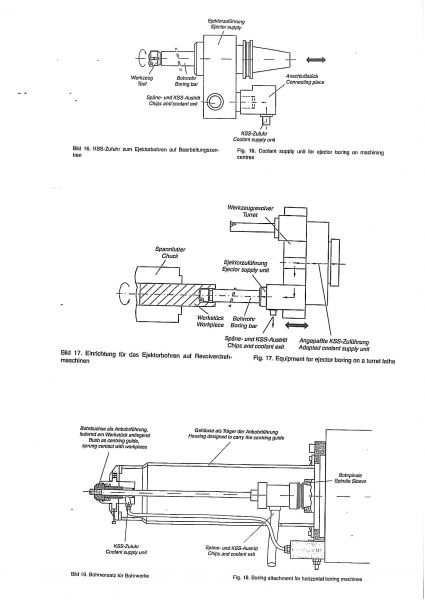
| • besondere Kühlschmierstoffzufuhr, z.B. Bild 16 | • special coolant supply units, e.g. Figure 16 and |
| und Bild 17 | Figure 17 |
| • Spritzschutz | • splash-proofing |
| Beim Einsatz auf Bohrwerken und Bearbeitungszen- | In the case of horizontal boring machines and ma- |
| tren ist die Bohrtiefe in jedem Fall eingeschränkt. | chining centres, the bore depth is always limited. |
| Bild 18 zeigt einen BTA-Bohrvorsatz für Bohr- | Figure 18 shows a BTA boring attachment for hor- |
| werke. | izontal boring machines. |
| 3 Werkzeuge | 3 Tools |
| 3.1 Werkzeugaufbau und Ausführungsarten | 3.1 Tool construction and designs |
| Die BTA-Bohrköpfe sind ein- oder mehrschneidig, | BTA boring heads are one- or multiple-edged,pro- |
| ggf. mit aufgeteilten Schneiden versehen, und haben | vided with split cutting edges, if required, and have at |
| mindestens zwei Führungsleisten. Diese Wirk- | least two guide pads. These functional elements can |
| elemente können gelötet (kleine Durchmesser) oder | be brazed (small diameters) or are exchangeable (di- |
| wechselbar (ab ca. Ø 18 mm) sein. | ameters of approximately 18 mm and above). |
| 3.1.1 Vollbohrwerkzeuge | 3.1.1 Drilling tools |
| Üblicher Bohrungsdurchmesser-Bereich: 6,3 mm | Common range of bore diameters: 6,3 mm to 18 mm |
| bis 18 mm (Werkzeuge mit Anschlußgewinde ab | (tools with connection thread diameters of 14 mm |
| Ø 14 mm). | and above). |
|
Praxisübliche Bohrungstoleranz*)
|
Praxisübliche Rz-Werte*)
|
Common bore tolerance*)
|
Common Rz values*)
|
|
|
IT 10 bis IT 8
|
16µm bis 5 µm
|
IT 10 to IT 8
|
16µm bis 5 µm
|
| *) Erreichbare Qualität u.a. abhängig vom Werkstückstoff und Kühl- | *)Achievable qualities depend, among other things, on the workpiece |
| schmierstoff | material and the coolant. |
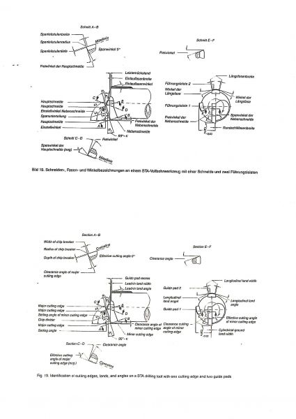
| Bild 19 zeigt ein Vollbohrwerkzeug mit einer | Figure 19 illustrates a drilling tool with one cutting |
| Schneide und zwei Führungsleisten. | edge and two guide pads. |
| Ein Vollbohrwerkzeug mit aufgeteilter Schneide und | A drilling tool with split cutting edge and two guide |
| zwei Führungsleisten ist ein Bild 20 dargestellt. | pads is illustrated in Figure 20. |
| In Bild 21 ist ein Werkzeug mit geklemmten | Figure 21 shows a tool with clamped cutting inserts |
| Schneidplatten und wechselbaren Führungsleisten | and exchangeable guide pads. |
| 3.1.2 Aufbohrwerkzeuge | 3.1.2 Boring tools |
| Üblicher Bohrungsdurchmesser-Bereich: 20 mm bis | Common range of bore diameter: 20 mm to |
| 1600 mm. Neben einer Vergrößerung des Druchmes- | 1600 mm. In addition to larger diameters, higher bore |
| sers werden bessere Bohrungsqualitäten erreicht, zie- | qualities are achieved. Moreover, pull boring serves |
| hendes Aufbohren dient außerdem zur Verminderung | to reduce exxentricity. |
| des Mittenverlaufes. |
|
Praxisübliche Bohrungstoleranz*)
|
Praxisübliche Rz-Werte*)
|
Common bore tolerance*)
|
Common Rz values*)
|
|
|
IT 10 bis IT 8 (IT 10 bis IT 9)**) |
16µm bis 5 µm (60µm bis 30 µm)**)
|
IT 9 bis IT 8 (IT 10 bis IT 9)**)
|
16µm bis 2 µm (60µm bis 30 µm)**)
|
| Erreichbare Qualität u.a. abhängig vom Werkstückstoff und Kühl- | *)Achievable qualities depend, among other things, on the workpiece |
| schmierstoff | material and the coolant. |
| Zum Prinzip des einschneidigen, stoßenden Aufboh- | Concerning the principle of one-edged, pushing bor- |
| rens siehe Bild 4, Bild 22 zeigt ein einschneidiges, | ing, see Figure 4. Figures 22 and 23 show a one- |
| Bild 23 ein mehrschneidiges Aufbohrwerkzeug. | edged and multiple-edged boring tool, respectively. |
| 3.1.3 Kernbohrwerkzeuge | 3.1.3 Trepanning |
| Üblicher Bohrungsdurchmesser-Bereich: 40 mm bis | Common range of bore diameter: 40mm to 630mm. |
| 630 mm. |
|
Praxisübliche Bohrungstoleranzen *) |
Praxisübliche Rz-Werte*) |
|
Common bore tolerance *) |
Common Rz values*) |
|
IT 10 bis IT 8 |
16 µm bis 5 µm |
|
IT 10 to IT 8 |
16 µm bis 5 µm |
| *)Erreichbare Qualitäten u.a. abhängig vom Werkstückstoff und Kühl- | *)Achievable qualities depend, among other things, on the workpiece |
| schmierstoff | material and the coolant |
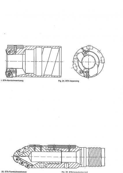
| Der Aufbau eines Kernbohrwerkzeuges ist in | The construction of a core-boring tool ist llustrated in |
| Bild 24 dargestellt. | Figure 24. |
| 3.1.4 Formbohrwerkzeuge | 3.1.4 Form-boring tools |
| Formbohrwerkzeuge werden nach Anforderung her- | Form-boring tools are tailor made. Possible bore di- |
| gestellt. Mögliche Bohrungsdurchmesser und er- | ameters and achievable qualities are specific and |
| reichbare Qualitäten sind spezifisch und müssen mit | shall be agreed with the manufacturer. |
| dem Hersteller abgestimmt werden. | |
| Der Aufbau eines Formbohrwerkzeuges ist in | The construction of a form-boring tool is illustrated |
| in Bild 25 dargestellt. | in Figure 25. |
| 3.2 Schneidstoffe, Führungs- und | 3.2 Cutting materials, guide pad and |
| Dämpfungsleistenmaterialien | damping pad materials |
| Für die Schneide bzw. Schneidplatten (häufig | For the cutting edges and inserts (often indexable in- |
| Wendeplatten) werden vorwiegend Hartmetalle der | serts), carbide of ISO group of tool application for |
| ISO-Zerspanungsanwendungsgruppe P bw. K über- | chip removal P or K, mostly coated, are the main ma- |
| wiegend beschichtet, eingesetzt. | terials in use. |
| Beschichtete Hartmetall-Wendeplatten dienen der | The use of coated carbide indexable inserts increases |
| Standzeitverlängerung. Dabei sollten auch die Füh- | the tool life. In this case the guide pads should also be |
| rungsleisten entsprechend beschichtet sein. | coated accordingly. |
| In Sonderfällen werden als Schneidstoffe auch HSS, | In special cases, HSS, cermets, ceramics, PCD or |
| Cermet, Keramik, PKD oder CBN verwendet. | CBN are used as cutting materials. |
| Als Werkstoff für Führungsleisten kommen ebenfalls | Carbides and cermets, also coated, are also used as |
| Hartmetalle und Cermets, auch beschichtet, zum Ein- | guide pad material. |
| satz. | |
| Je nach Ausführung werden sie im Werkzeuggrund- | Depending on the design, the guide pads are fastened |
| körper durch Schrauben, Klemmen oder Löten befe- | to the tool body by screwing, clamping, or brazing. |
| stigt. | |
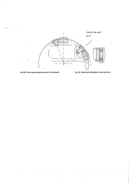
| Führungsleisten aus Keramik (Vollmaterial), PKD | Guide pads of ceramics (solid material), PCD, and |
| und CBN (in Stahlkassetten) sind meistens geklemmt | CBN (in steel cassettes) are clamped in most cases |
| (Bild 26). | (Figure 26). |
| Für Dämpfungsleisten werden verschleißfeste Kunst- | Damping pads are made of wear-resistant plastic |
| stoffmaterialien wechselbar befestigt. | materials and are so fastened as to allow their ex- |
| changing. |
| 4. Verfahren zur Erzeugung von | 4. Procedures for the manufacture of |
| Sonderkonturen | special contours |
| Es gibt Werkstücke mit tiefen Bohrungen, deren | There are workpieces with deep bores, whose inner |
| Innenkonturen rotationssymmetrisch, aber nicht | contours are rotationally symmetric but not cylindri- |
| durchgängig zylindrisch sind. | cal over the entire length. |
| Beispiele für Werkstücke mit Konturen ohne Hinter- | Examples of workpieces with contours without un- |
| schneidungen sind: | dercuts are: |
| • Schleudergußkokillen | • centrifugal casting moulds |
| • konische Bohrungen in Extruderzylinder | • conical bores in extruder cylinders |
| Oftmals sind die erforderlichen Innenkonturen mit | Often, the inner contours required can be manufac- |
| BTA-Formwerkzeugen nur sehr aufwendig herstell- | tured by means of BTA form tools at great expense |
| bar. | only. |
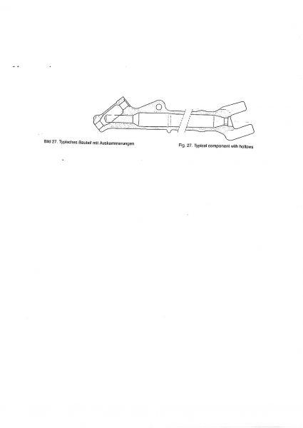
| Beispiele für Werkstücke mit Konturen mit Hinter- | Examples of workpieces with contours with under- |
| schneidungen sind: | cuts are: |
| • Triebwerkswellen (Auskammerungen zur Ge- | • propeller shafts (hollows for reduced weight) |
| wichtserleichterung) | |
| • Landebeine (Auskammerungen zur Gewichts- | • landing gear (hollows for reduced weight), |
| erleichterung) Bild 27 | Figure 27 |
| • weitere Bauteile, insbesondere aus der Luft- und | • further components, especially for use in aeronau- |
| Raumfahrttechnik | tics and aerospace |
| Diese Innenkonturen sind mit BTA-Formwerkzeugen | These inner contours cannot be manufactured using |
| nicht herstellbar. In solchen Fällen bietet sich an, | BTA from tools. In such cases, it is convenient to use |
| Werkzeuge einzusetzen, deren Schneiden und ggf. | tools whose cutting edges and, if required, guide pads |
| Führungsleisten verstellbar ausgeführt sind. | are adjustable. |
| Zum Einsatz solcher Werkzeuge ist eine (BTA-) Vor- | A (BTA) rough-bore of high quality is prerequisite to |
| bohrung hoher Güte erforderlilch. | the use of such tools. |
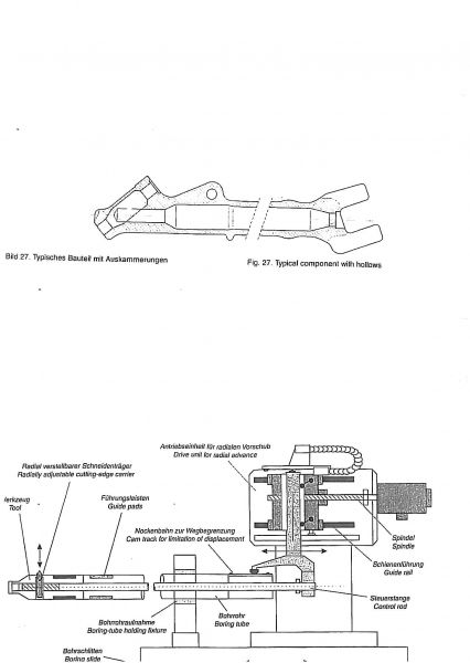
| NC-gesteuerte Tiefbohrmaschinen bieten die Mög- | NC deep-boring machines provide for a futher NC |
| lichkeit der Erweiterung um eine weitere NC-Achse, | axis wich allows controlling the tool diameter as a |
| die den Werkzeugdurchmesser in Abhängigkeit von | function of the bore depth. Figure 28 shows a sche- |
| der Bohrtiefe regelt. Bild 28 zeigt den schemati- | matic of such a drive and tool system. |
| schen Aufbau eines solchen Antriebs- und | |
| Werkzeugsystems. | |
| Durch axiale Verschiebung der im Bohrrohr liegen- | The position of the cutting edge is changed by axial |
| den Steuerstange wird die Lage der Schneide verän- | displacement of the control rod inside the boring |
| dert. Die Führungsleisten können ebenfalls, z.B. | tube. The guide pads can also be adjusted, e.g., |
| hydraulisch, angestellt werden. | hydraulically. |
| 5. Richtwerte | 5. Reference values |
| 5.1 Maschinen-Antriebsleistung | 5.1 Machine drive rating |
| Besondere Aufmerksamkeit ist der Wahl einer ausrei- | Special care shall be taken to select a sufficient drive |
| chenden Antriebsleistung zu widmen. Eine Hilfestel- | rating. For BTA deep hole boring of steel, the dia- |
| lung für das BTA-Tiefbohren von Stahl bietet das | gram shown in Figure 29 offers guidance. For mul- |
| Diagramm in Bild 29. Bei mehrschneidigen Werk- | tiple-edge tools and combined procedures (e.g. bor- |
| zeugen und Kombinationsverfahren (z.B. Aufboh- | ing, skiving and roller burnishing), other relations |
| ren, Schälen und Glattwalzen) gelten andere Zusam- | apply. In this case, the tool manufacturer shall always |
| menhänge, hier ist in jedem Fall der Werkzeug- | be consulted. |
| hersteller zu konsultieren. |
| 5.2 Kühlschmierstoff-Volumenstrom und -Druck | 5.2 Coolant volume flow and pressure |
| Nichtwassermischbare Kühlschmierstoffe, soge- | Straight so-called deep-boring oils, are preferred in |
| nannte Tiefbohröle, werden in der Praxis bevorzugt | practice. Figures 30 and 31 illustrate the coolant |
| eingesetzt. In Bild 30 ist in Abhängigkeit vom | volume flow and pressure, respectively, as a function |
| Bohrungsdurchmesser der Volumenstrom und in | of the bore diameter. For short-chipping materials. |
| Bild 31 der KSS-Druck angegeben. Für kurzspa- | volume flow and pressure may be chosen according |
| nende Werkstoffe können Volumenstrom und Druck | to the lower curves. |
| nach den unteren Kurven gewählt werden. | |
| Die Temperaturen des Tiefbohröls sollten 50°C nach | If possible, the temperature of the deep-boring oil |
| Möglichkeit nicht überschreiten, da sich die Eigen- | should not exceed 50°C, since the characteristics of |
| schaften des KSS bei höheren Temperaturen ändern | the coolant may change above this temperature. |
| können. | |
| Bei wassergemischten KSS, z.B. Emulsionen, liegt | For aqueous, e.g. emulsions, the pressure at the same |
| der KSS-Druck bei gleichem Volumenstrom bei | volume flow is approximately two thirds of the value |
| ca. 2/3 des im Diagramm angegebenen Wertes. | indicated in the diagram. |